






















FAQ Maintenance Guideline from GeoDAS
1. Introduction
- This procedure describes a typical monthly check of a GeoSIG system. It will give some basic information about the state of recorder and sensor.
2. Required Tools
- Recorder and Sensor you want to check, running and connected to network
- Access to GeoDAS server (computer with GeoDAS the recorder is connecting to)
3. Check for existing Procedures
- Please check if there is a project-specific procedure for your system to follow instead—especially if your system is tied to an alarm system, as the execution of the test pulse described in this procedure may cause an alarm.
4. Access the latest Status Information
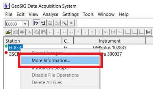
- In GeoDAS window Stations: General Information, right-click on the station and choose More Information...
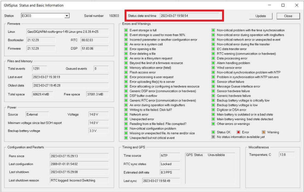
- Make sure the field Status date and time shows a recent date
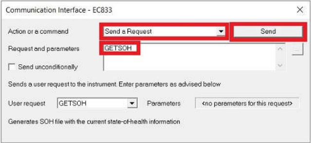
- If it is outdated, you can request new information from GeoDAS window Stations: General Information. Right-click on the station and choose Instrument Control... -> Send a Request -> GETSOH -> [Send]
5. Check Errors and Warnings
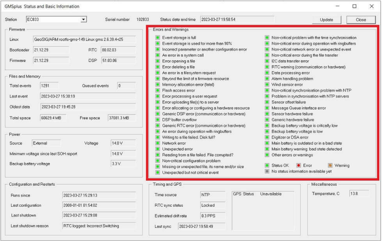
- Check the Field Errors and Warnings and make sure no errors are present (all bullets green)
6. Check Battery Voltages
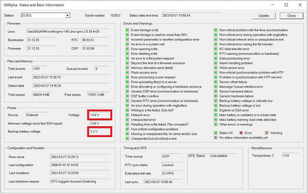
- Check the field Power
- If the recorder is powered from AC (Source External), Voltage should at least show 13.5V
- If your recorder (only GMS-xx, GMSplus and fora) has a backup battery, the Backup battery voltage should be at least 3.0V
- Main battery should be replaced every 3 years (See Warnings and Safety in User Manual)
- Backup battery should be replaced every 5 years (See Warnings and Safety in User Manual)
- To set battery installation date:
In GeoDAS window Stations: General Information, right-click on the station and choose Instrument Control... -> Send a Request -> SETBATDATE yyyy-mm-dd -> [Send]
or from the web interface under Status and Maintenance -> Maintenance
or through the serial console in Test and Configuration Menu -> T - Battery installation dates
7. Check Time Synchronisation
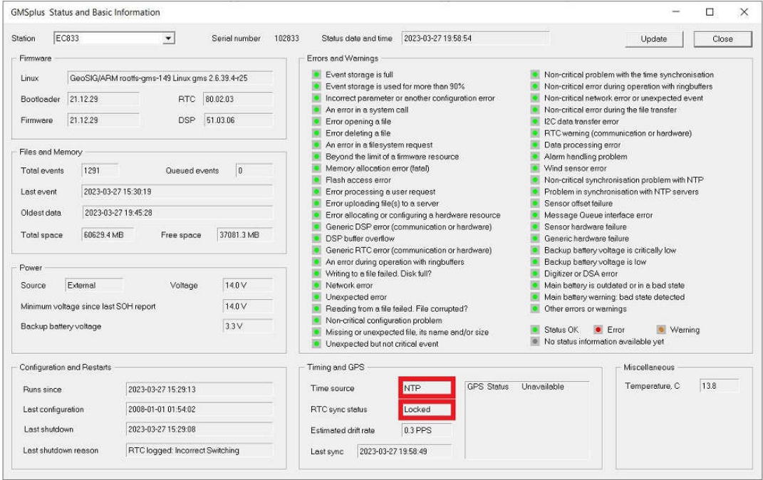
- Check the field Timing and GPS
- Time source should show NTP or GPS (whenever possible, an external time source such as NTP or GPS should be used)
- RTC sync status should show Locked
8. Remove offset
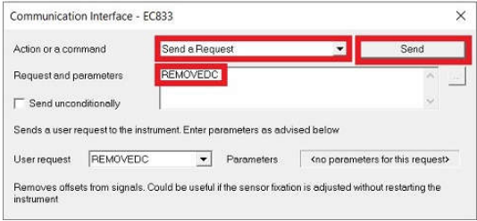
- In GeoDAS window Stations: General Information, right-click on the station and choose Instrument Control... -> Send a Request -> REMOVEDC -> [Send]
9. Request Test Puls
- In GeoDAS window Stations: General Information, right-click on the station and choose Instrument Control... -> Send a REquest -> TSTSENSOR 1 -> [Send]
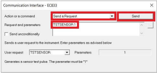
- A miniseed file with the recorded pulse (file prefix CAL_) will be uploaded to the Data folder of your station in GeoDAS (C:\GeoDAS_DATA\Data\)

10. Check Test Pulse
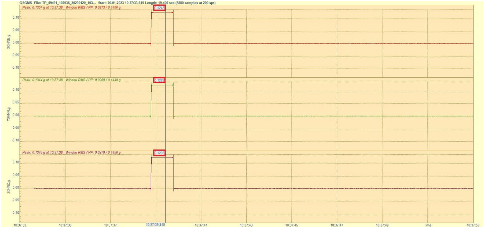
- The shape of the test pulse depends on the sensor type. A reference pulse recorded at the factory is shipped for each sensor on the usb key; the file can be found in the folder Calibation\Test_files_Sensors (file of the sensor). It is also recommended to record a test pulse after installation and keep it with later records for comparison.
- Double-click the file to open it in GeoDAS
- Click into the yellow part of the window to make the cursor appear
- Move the cursor to the flat part of the pulse
- Check that the value of the flat part for each axis is within the range of 0.115g-0.1375g
10.2 Test pulse of AC-2x
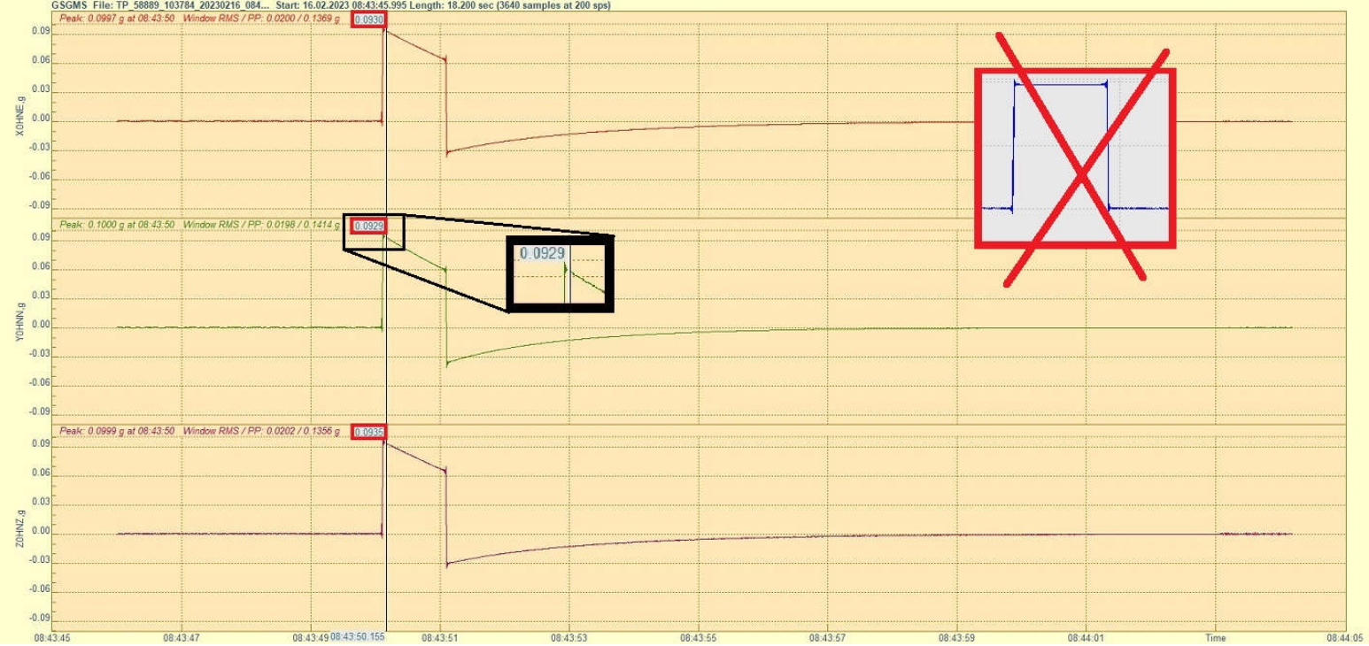
- Double-click the file to open it in GeoDAS
- Click into the yellow part of the window to make the cursor appear
- Move the cursor right after the peak, the point that forms the beginning of a straight line with some slope
- Check that the value right after the peak for each axis is within the range of 0.09g-0.11g
- Visually check that the angle of the slope is similar on all axes (compare with a reference pulse file if unsure)
10.3 Test pulse of AC-4x
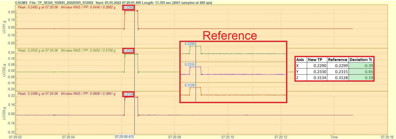
- Double-click the file to open it in GeoDAS
- Click into the yellow part of the window to make the cursor appear
- Move the cursor to the flat part of the pulse, x- and y-axis should show a similar value; the z-axis should show a higher value
- Open a reference file of the same sensor and check that the flat part for each axis on the newly recorded pulse does not deviate more than +/-10%
10.4 Test pulse of AC-6x
- Double-click the file to open it in GeoDAS
- Click into the yellow part of the window to make the cursor appear
- Move the cursor to the flat part of the same pulse. Depending on the sensor generation, the pulse may be negative or positive
- Open a reference file of the same sensor and check that the flat part for each axis on the newly recorded pulse does not deviate more than +/-10%
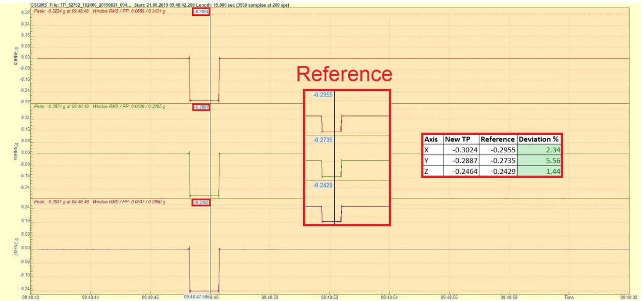
10.5 Test pulse of VE-1x
- Double-click the file to open it in GeoDAS
- Click into the yellow part of the window to make the cursor appear
- Check that the pulse is with similar shape as shown in the picture below
- Move the cursor to the peak of the positive pulse to read the value for each axis
- Open a reference file of the same sensor and check that the peak for each axis on the newly recorded pulse does not deviate more than +/-10%
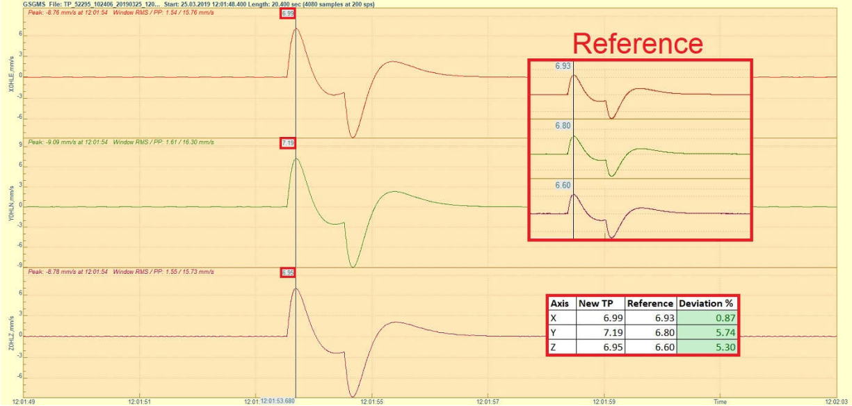
10.6 Test pulse of VE-2x
- Double-click the file to open it in GeoDAS
- Click into the yellow part of the window to make the cursor appear
- Check that the pulse is with similar shape as shown in the picture below
- Move the cursor to the peak of the positive pulse to read the value for each axis
- Open a reference file of the same sensor and check that the peak for each axis on the newly recorded pulse does not deviate more than +/-10%
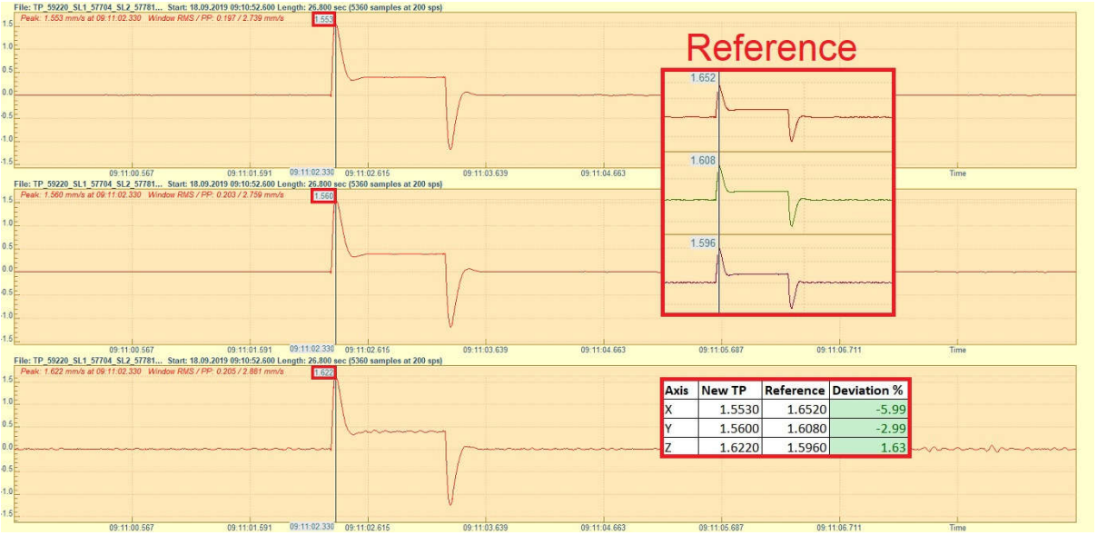
10.7 Test pulse of VE-5x-SP
- Double-click the file to open it in GeoDAS
- Click into the yellow part of the window to make the cursor appear
- Check that the pulse is with similar shape as shown in the picture below
- Move the cursor to the peak of the positive pulse to read the value for each axis
- Open a reference file of the same sensor and check that the peak for each axis on the newly recorded pulse does not deviate more than +/-10%
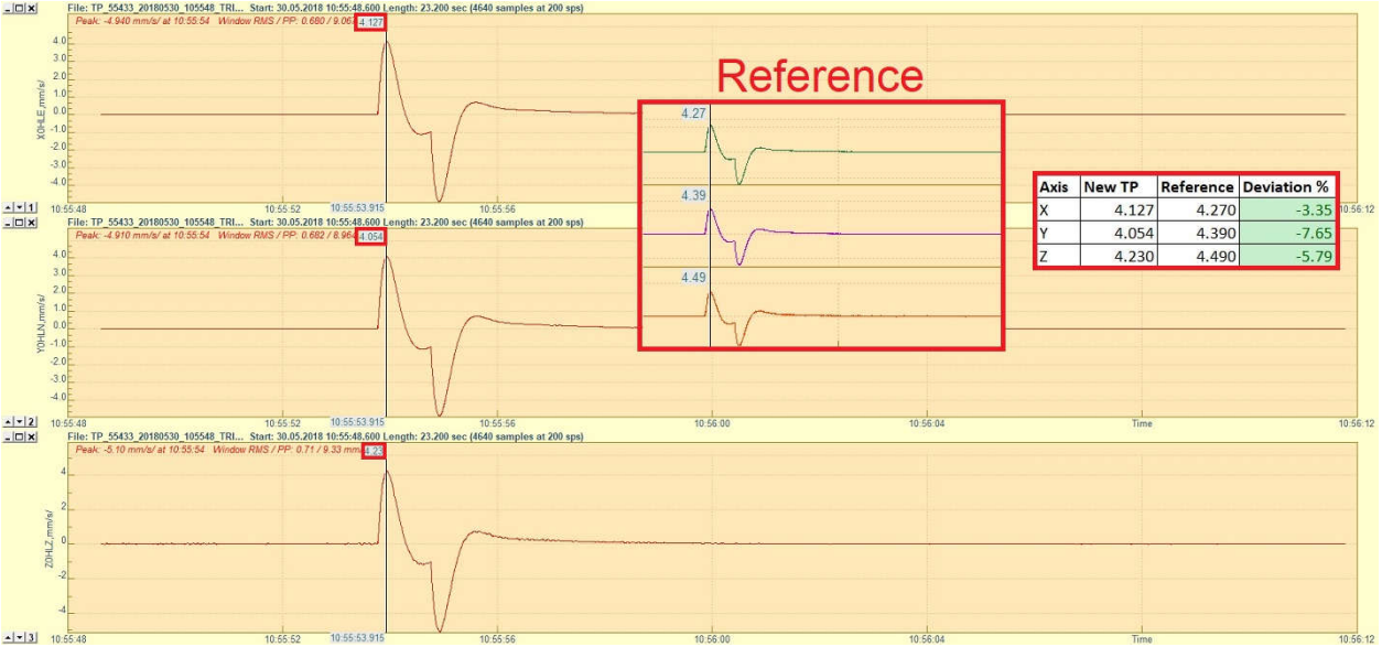
10.8 Test pulse of VE-5x-BB
- Double-click the file to open it in GeoDAS
- Click into the yellow part of the window to make the cursor appear
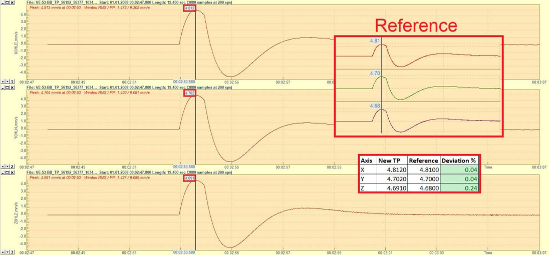
- Check that the pulse is with similar shape as shown in the picture below
- Move the cursor to the peak of the positive pulse to read the value for each axis
- Open a reference file of the same sensor and check that the peak for each axis on the newly recorded pulse does not deviate more than +/-10%