






















FAQ Maintenance Guidelines from Recorder Serial Console
1. Introduction
- This procedure describes a typical monthly check of a GeoSIG system. It will give some basic information about the state of recorder and sensor.
2. Required Tools
- Recorder and Sensor you want to check
- Computer, connected to Recorder Serial Console with ucon
- SD-Card reader and software to read test pulse files recorded in miniseed format (GeoDAS is recommended
3. Check for Existing Procedures
- Please check whether there is a project-specific procedure for your system to follow instead -- especially if your system is tied to an alarm system, as the execution of the over range test described in this procedure may cause an alarm.
4. Check Errors and Warnings
- In the main menu, check that no errors or warnings are present (both brackets show (0) )
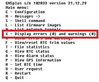
- If there are errors or warnings, you can show more information by pressing [X]
5. Check Battery Voltages
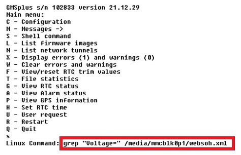
- In the Main Menu, select [S] to enter Shell Command Prompt
- Enter grep "Voltage=" /media/mmcblk0p1/websoh.xml (case sensitive) and confirm with [Enter]
- If the recorder is powered from AC (ACPower="ON"), Voltage= should at least show 13.5V
- If your recorder (only GMS-xx, GMSplus and fora) has a backup battery, the Backup Voltage= should be at least 3.0V
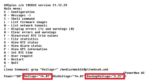
- Main battery should be replaced every 3 years (See Warnings and Safety in User Manual)
- Backup battery should be replaced every 5 years (See Warnings and Safety in User Manual)
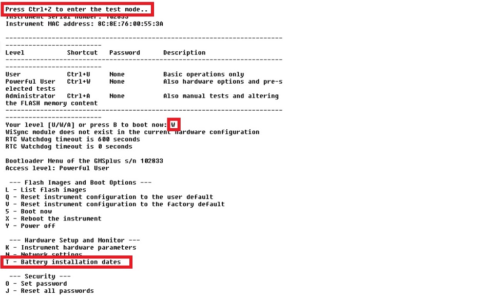
- To set battery installation date:
In Test and Configuration Menu -> T - Battery Installation dates (enter the menu pressing [Ctrl]+[Z] when prompted during startup)
6. Check Time Synchronisation
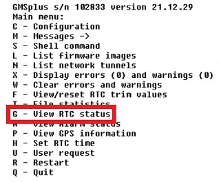
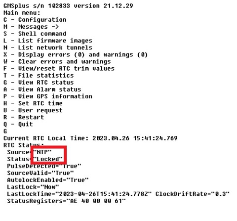
- In the Main Menu, select [G] to view RTC status
- Source should show NTP or GPS (whenever possible, an external time source such as NTP or GPS should be used)
- Status should show Locked
7. Remove offset
- In the Main Menu, select [U] to enter a User request
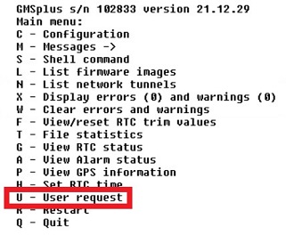
- Enter command REMOVEDC and confirm by pressing enter
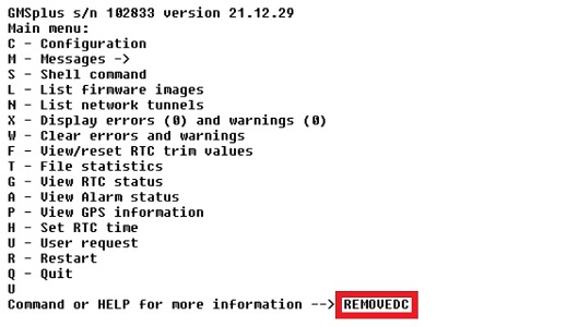
- Wait until the operation is completed
8. Request Test Pulse
- In the main Menu, select [U] to enter a User request
- Enter command TSTSENSOR 1 and confirm by pressing enter

9. Copy Data from SD Card
9.1 Turn off the Recorder
- Turn off the recorder by pressing the power button for 3 seconds
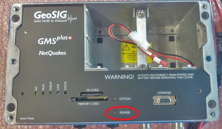
- Wait until the RUN LED stops flashing
- Remove the SD card from its slot (push to release)
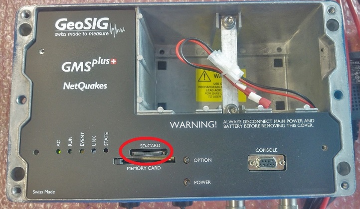
9.3 Connect SD Card to Computer
- Insert the SD card in your PC's card slot
- Windows cannot detect all partitions on the SD card, so it may ask you to format the card. PLEASE DO NOT FORMAT THE CARD, OTHERWISE ALL RECORDED DATA WILL BE LOST!
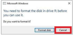
- Press [Cancel] if the above message appears
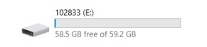
- The SD card should appear as drive named with the serial number of the recorder
9.4 Copy Test Pulse File
- Check the Data folder on the SD card and look for the latest miniseed file with the recorded pulse (file prefix CAL_)

- Copy the file and past it to a directory of your computer. (Remember the location for the check under 10.)
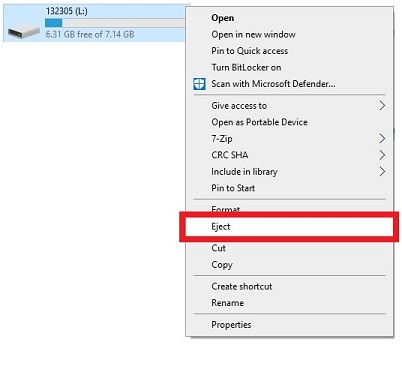
- Safely remove the drive (Right-click -> Eject)
9.6 Mount SD Card in Recorder
- Insert the SD card back in the recorder's card slot and turn it on by pressing the power button
10. Check Test Pulse
- The shape of the test pulse will depend on the sensor type. A reference pulse recorded at the factory is shipped for each sensor on the usb key. The file can be found in the folder Calibration\Test_files_Sensors (file prefix TP_ with the SN of the sensor). It is also recommended to record a test pulse after installation and keep it with later records for comparison.
10.1 Test pulse of AC-7x
- Double-click the file to open it in GeoDAS
- Click into the yellow part of the window to make the cursor appear
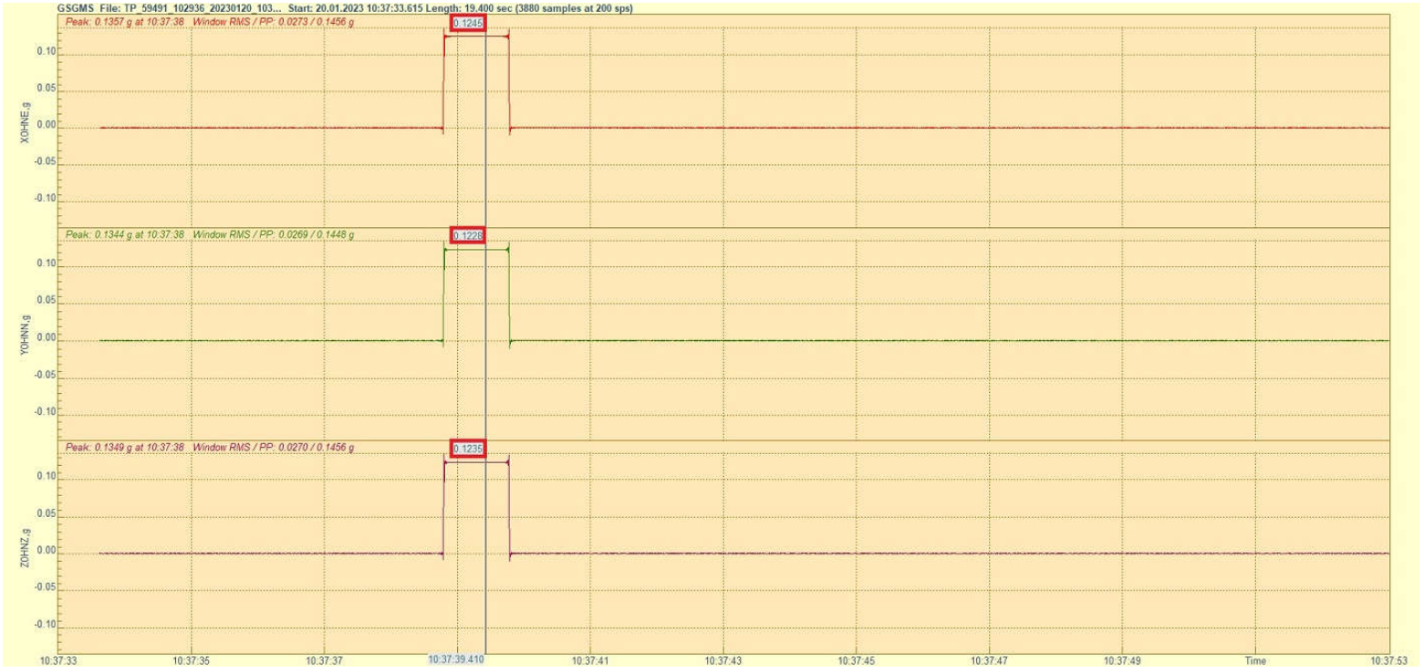
- Move the cursor to the flat part of the pulse
- Check that the value of the flat part for each axis is within the range of 0.1125g-0.1375g
10.2 Test pulse of AC-2x
- Double-click the file to open it in GeoDAS
- Click into the yellow part of the window to make the cursor appear
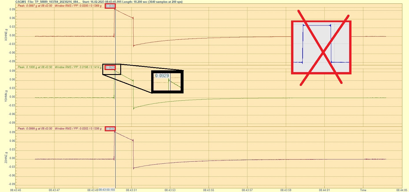
- Move the cursor right after the peak, the point that forms the beginning of a straight line with some slope
- Check that the value right after the peak for each axis is within the range of 0.09g-0.11g
- Visually check that the angle of the slope is similar on all axes (compare with a reference pulse file if unsure)
10.3 Test pulse of AC-4x
- Double-click the file to open it in GeoDAS
- Click into the yellow part of the window to make the cursor appear
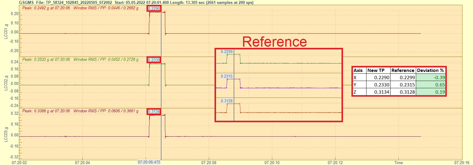
- Move the cursor to the glat part of the pulse; x and y-axis should show a similar value, and z-axis should show a higher value
- Open a reference file of the same sensor and check that the flat part for each axis on the newly-recorded pulse does not deviate more than +/-10%
10.4 Test pulse of AC-6x
- Double-click the file to open it in GeoDAS
- Click into the yellow part of the window to make the cursor appear
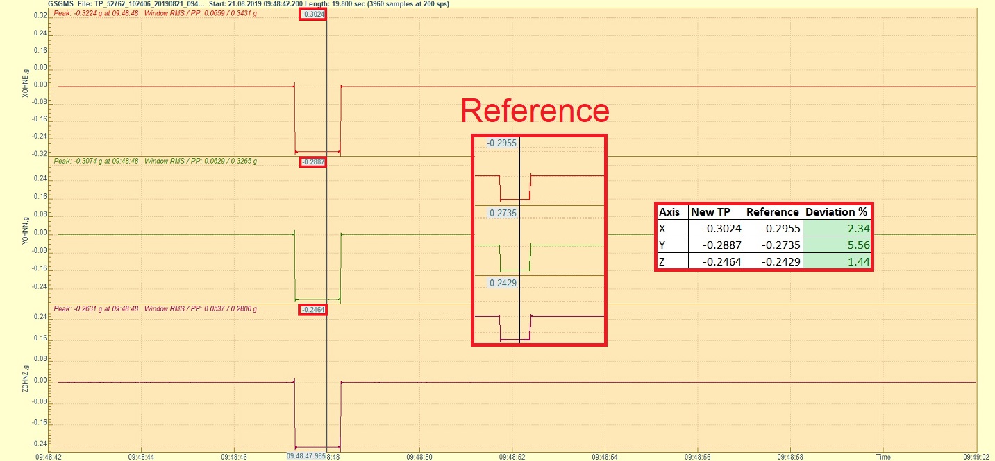
- Move the cursor to the flat part of the pulse. Depending on the sensor generation, the pulse may be negative or positive
- Open a reference file of the same sensor and check that the flat part for each axis on the newly-recorded pulse does not deviate more than +/-10%
10.5 Test pulse of VE-1x
- Double-click the file to open it in GeoDAS
- Click into the yellow part of the window to make the cursor appear
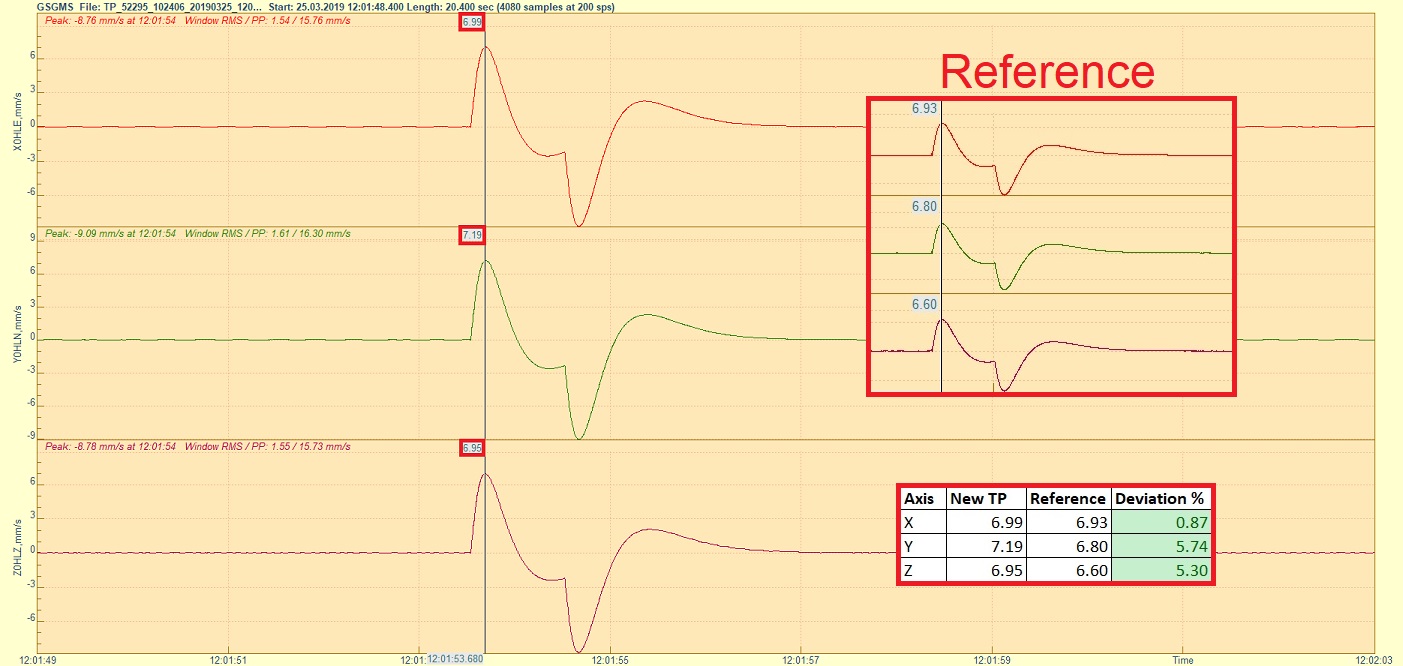
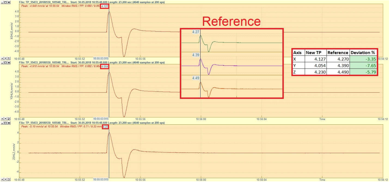
- Check that the pulse has a similar shape as shown in the picture below
- Move the cursor to the peak of the positive pulse to read the value for each axis
- Open a reference file of the same sensor and check that the flat part for each axis on the newly-recorded pulse does not deviate more than +/-10%
10.6 Test pulse of VE-2x
- Double-click the file to open it in GeoDAS
- Click into the yellow part of the window to make the cursor appear
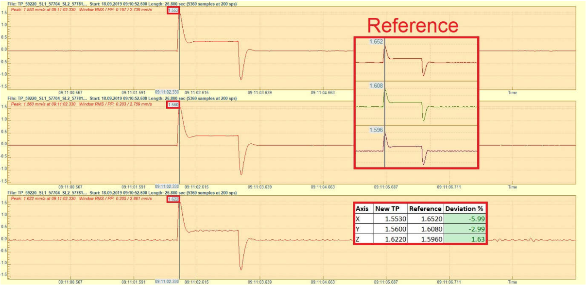
- Check that the pulse has a similar shape as shown in the picture below
- Move the cursor to the peak of the positive pulse to read the value for each axis
- Open a reference file of the same sensor and check that the flat part for each axis on the newly-recorded pulse does not deviate more than +/-10%
10.7 Test pulse of VE-5x-SP
- Double-click the file to open it in GeoDAS
- Click into the yellow part of the window to make the cursor appear
- Check that the pulse has a similar shape as shown in the picture below
- Move the cursor to the peak of the positive pulse to read the value for each axis
- Open a reference file of the same sensor and check that the flat part for each axis on the newly-recorded pulse does not deviate more than +/-10%
10.8 Test pulse of VE-5x-BB
- Double-click the file to open it in GeoDAS
- Click into the yellow part of the window to make the cursor appear
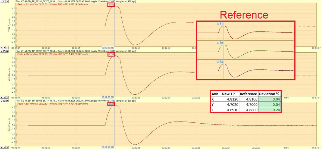
- Check that the pulse has a similar shape as shown in the picture below
- Move the cursor to the peak of the positive pulse to read the value for each axis
- Open a reference file of the same sensor and check that the flat part for each axis on the newly-recorded pulse does not deviate more than +/-10%