Humber Bridge
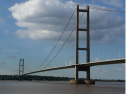
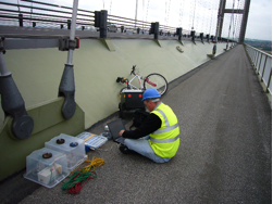
When opened in 1981 the Humber Bridge in the UK was the largest single span bridge in the world with a total length of 2220 metres. The road distance in the UKbetween Hull and Grimsby was reduced by nearly 80km (50 miles) as a result of this transportation achievement. Where the UK leads the rest of the world eventually follows and the Humber Bridge in the UK is now statistically placed 5th place, the 4 ahead (in alphabetical order) now being Akashi-Kaikyo, Great Belt, Runyang and Xihoumen. The Humber Bridge, however, still remains the largest bridge with a lower level foot and cycle path on both sides. Bridge monitoring has since moved into the 21st century with technology changes that have moved away from analogue to digital bridge monitoring solutions.
Such new technologies bring with them the need re-evaluate the most suitable monitoring solutions and in this instance re-evaluations were necessary on the modal properties of the Humber Bridge alongside the viability of using stand alone recorders with provision timing (via GPS) to provide histories of response within the analysis of such an extended open space structure. The Humber Bridge as designed can tolerate constant motion and bends more than 3 metres in winds of 129 km/hr (80 mph) at which point safety factors emerge but the towers, although both vertical, are not parallel, these being under 50mm further apart at the top than at the bottom.
An international team comprising:
- Prof. JMW Brownjohn, University of Sheffield, UK
- Dr. Paul Reynolds, University of Sheffield, UK
- Mr. Chris Middleton, University of Sheffield, UK
- Mr. Filipe Magalhaes, FEUP Porto, Portugal
- Prof. Elsa Caetano, FEUP Porto, Portugal
- Prof. Ivan Au, City University Hong Kong
- Prof. Paul Lam, City University Hong Kong
with support from Dr. Ivan Munoz Diaz, Prof. Aleksandar Pavic, Dr. Stana Zivanovic, Mrs. Eunice Lawton, Mrs. Tuan Norhayati Tuan Chik and Mr. Mohammad Muaz Aldimashki from Sheffield, Prof. Alvaro Cunha from FEUP and Mr John Cooper, Mr Peter Hill and Mr Ian Allenby from Humber Bridge Board tested the bridge during the week 14th-18th July 2008 as part of EPSRC funded research project:
EP/F035403/1, Novel Data Mining and Performance Diagnosis Systems for Structural Health Monitoring of Suspension Bridges.
- To re-evaluate the modal properties of the bridge and provide a modal model in digital form, that would be used as a baseline for calibration of a finite element model of the bridge
- To evaluate the viability of using standalone recorders with precision timing (via GPS) to provide time histories of response that could be used for operational modal analysis of such an extended open-space structure
- To evaluate the difficulties of operational modal analysis procedures in estimating modal parameters for super-low frequency structures with short data lengths and to evaluate the effect of non-stationary structural (hence modal) parameters on the procedure of gluing mode shape pieces.
The 1985 test used only three Schaevitz LSOC accelero-meters, about 2 km of cable, a two channel spectrum analyzer and a four-channel analog tape recorder. The testing lasted two weeks, and data processing to identify the modes, replaying data tapes through the spectrum analyzer and using the procedure known as ‘peak picking’ lasted about 6 months. The analog tapes can no longer be read and the digital modal description did not survive migration between storage formats in the last 23 years. Hence while the mode frequencies and general form of most of the mode shapes are useful these are not available digitally.
Also the resolution was poorer, the damping ratio estimates are known to be heavily biased due to the crude technology, the signal to noise ratios of the sensors are poor and, made worse by the poor dynamic range of the tape recorder, the torsional mode shapes could not be resolved using only three sensors and it was not possible to measure simultaneously points on towers, main span and side spans. So there are several reasons to need an up to date study.
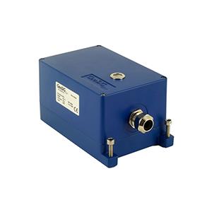
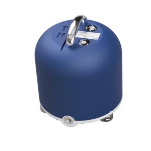
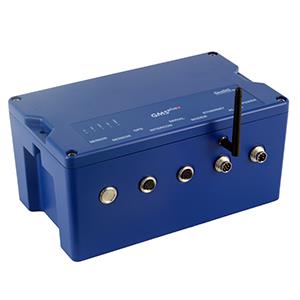
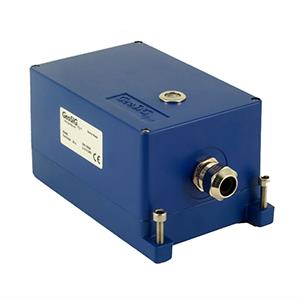
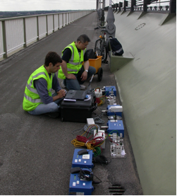
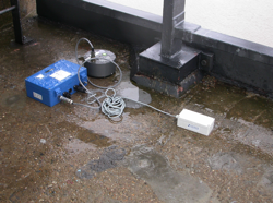
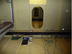
The new study involved new instruments consisting of ten GSR-24’s utilising internal or external accelerometers, all brought together from FEUP and Sheffield.
The testing was divided into 28 measurements spanning five days: For example on day 2, measurements concentrated on the southern part of the bridge, in the direction of the town of Barton. Each of the box sections of the bridge, are identified by an odd number with prefix b (for Barton, south) or h (for Hessle, north). Recordings were made mainly at alternate hanger locations, in each case maintaining at least one fixed (reference) location on the main span. The set of seven measurements on day 2 listed below used a reference pair (21h) on the Hessle side and one (49b) on the Barton side, with the remaining three pairs of recorders roving on the Barton side with 10-minutes to relocate between one-hour recordings.
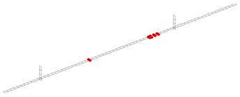
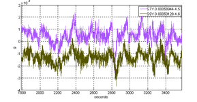
Measurements included one at the Barton tower (78b) with including locations 77b/79b across the bearings, then moved into the Barton side span. Measurement setup 14a was a short recording to cross-check calibrations (as shown in Figure 3). The configuration for measurement setup 9 is shown in Figure 4 the red dots indicate the 10 recorder locations.


