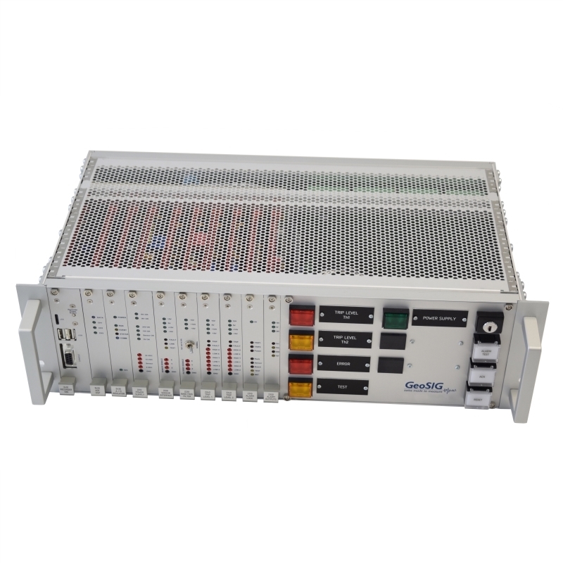
GeoSIG STS
Key Features
- High reliability by using only analog signal and hardware for the trip signal
- Field proven GeoSIG accelerometer
- Trip on any individual sensor axis or on any vector sum of axes
- Highly flexible analog filtering for the sensor signal to fit project requirements
- Testable analog full chain from sensor up to alarm output
- Permanent monitoring of the connection to the sensor
- Easy maintenance and simple troubleshooting with rich number of test points and indicators
- Protected against misuse with key switch and permanent monitoring
- Permanent digital recording of full waveform
- Digital recorder based on field proven GeoSIG fora system
- Realtime streaming of digital waveform and system status through Ethernet or Serial interface
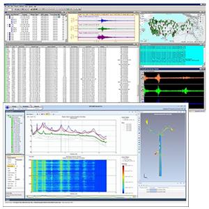
- Comprehensive dedicated software package
- Easily integrated in a standard 19" rack
- Independent and autonomous
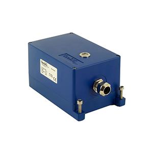
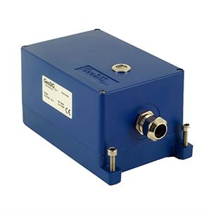
STS is a state-of-the-art seismic switch / trip system packaged as a 19’’ rack module consisting of Slot-in Modules (SiMs) inserted into vertical slots with a remote accelerometer connected to it. It provides a set of highly reliable alarm contacts as outputs activated by exceedance of acceleration and/or based on state of health. The STS combines the best of the analog and digital technologies by utilising only hardware for the highly reliable alarms, and digital data acquisition for realtime digital monitoring, recording, playback, in-depth processing and archiving of the sensor signal. The unit provides full traceability of the sensor signal as well as the system logs—even if no trip was activated—with a buffer spanning to several weeks back. All of the digital information can also be provided to remote users in real time, on demand, continuously and/or periodically.
Applications include:
Applications include:
- Automatic Seismic Trip System (ASTS)
- Detectors for integration in an ASTS
- Connection to an emergency shutdown system
- Nuclear Reactor protection
- Power Plant protection / stop
- Industrial Process protection / stop
-
Sensor
- Model
- STS-AC73 *
- Type
- True Electro-mechanical Force Balance Accelerometer
- Dynamic Range
- 165 dB (per bin rel. full range)
- Bandwidth
- DC to 200 Hz Cross Axis Sensitivity: < 0.5 %
- Protection
- IP66 stainless steel protective housing
- Power
- 24 VDC from STS module
- Signal transmission
- Current loop 4 to 20 mA
-
*Other sensor models are available on request
-
STS Rack – Analog Modules
POWER SUPPLY SiM
- DC input
- 24 VDC (9 - 36 VDC) with DC/DC insulation
- Power
- 30 W max
SENSOR INTERFACE SiM
- Input Channels
- 3 (for triaxial sensor)
- Input Signal
- 4 - 20 mA current loop
- Sensor Power
- 15 or 24 VDC
ANALOG FILTERS SiM
- Type
- Highpass (HP) and Lowpass (LP) up to 6 poles each
- Bandwidth
- 0.5 - 10 Hz by default, adjustable per project
- Test mode
- Filter disable switch for testing
TRIP LEVEL 1 / 2 COMPARATOR SiM
- Comparators
- One per each sensor axis, totally 3
- Optional
- Vector calculation (analog) before comparison
- Level adjustment
- By potentiometers and dip-switches
- Verification of settings
- Test points on front panel
ALARM LOGIC SiM
- Type
- Fully discrete, no firmware
- Numbers of alarms
- 4, each with jumper selectable source
- Restart
- A restart timer is used to avoid random condition during power up, especially for low trip level having an HP filter set to a low frequency
- Control panel
- Test, Acknowledge, Reset buttons for alarms with security key
- Status lamps
- One per each alarm and power status
ALARM OUTPUTS SiM
- Coil status
- Normally energized or not, user selectable
- Hold timer
- Selectable from 0.8 to 5, 15 or 30 seconds
- Alarm type
- Latched with acknowledge/reset or hold time
RELAYS INTERFACE BOARD
- Relays type
- Solid state opto-relays
- Contacts type
- 2 inverters
- Contact verification
- Resistors in parallel and series
-
STS Rack – Digital Modules
DATA HANDLING SiM
- Data Recording
- Continuous and/or event trigger based
- Trigger Type
- Level or STA/LTA trigger
- Pre- / Post-event-Time
- 1 to 720 / 1 to 7200 seconds, typical
- Trigger filtering
- User configurable LP, HP or bandpass (BP)
- Data Stream
- GSBU, SeedLink (Earthworm compatible)
- Storage Memory
- 64 GByte removable microSD Card, or higher with policy based intelligent management
- Recording format
- miniSEED, optionally with extended information encapsulated into blockette 2000
DIGITISER SiM
- Channels
- 3 channels per SiM (for triaxial sensor)
- A/D Converter
- 24 Bit D-S per channel with FIR anti-aliasing
- Sampling Rate
- Up to 1000 SPS
INTERFACE DIGITAL/ANALOG
- Type
- Unidirectional analog to digital with insulation
-
Self-Test and Self-Monitoring (Analog and Digital)
The ERROR alarm by analog part:
The alarm can be activated from various sources: a board is removed, a power supply has an under-voltage condition, a sensor signal is in error or an alarm SiM has a permanent trip.
TEST alarm by analog part:
When the TEST button is pressed on the unit, an alarm is activated. Same if the test line to sensor activated for any reason or the filter switch set to disabled mode.
Digital part:
The digital part receives the alarms status and sends it with the measured acceleration signal to the communication channel. A SOH is built by the digital system and transmitted to the user.
-
Time base (Digital)
- Internal
- Intelligent Adaptive Real Time Clock (IARTC)
- External
- NTP (requires Ethernet connection)
- Std. TCXO accuracy
- ±0.5 ppm (15 s/year) @ +25 °C
- Accuracy with NTP
- < ±4 ms typical, assuming reasonable access to NTP servers
-
Communication Channel (Digital)
- Standard
- Ethernet TCP/IP for streaming and SSH or web interface access.
- Optional
- Serial port for unidirectional streaming data and system status
-
User Interface (Analog and Digital)
Analog
Clear indicators and push-buttons allow the operator to easily perform tasks. The unit is also made to operate independently from any operator action. The front panel is populated with test points and indicators to simplify maintenance and troubleshooting tasks. The setting of the trip system (levels, duration, …) is achieved by adjusting potentiometers.
Digital
An intuitive web interface is available for easy configuration with any web browser. Alternatively the configuration file in XML format can be edited on site through the instrument console, exchanged by replacing the memory card, remotely from a server or through SSH. Even if the configuration file can be manually edited at any time, a tool is provided to edit it securely.
When using the serial port for sending data (streaming) and status to an archiving system, the system can be operated only locally through the front panel serial console or connecting directly to the Ethernet port. This gives the full control of the digital part of the system only locally. At all times the analog part remains independent.
When using the serial port for sending data (streaming) and status to an archiving system, the system can be operated only locally through the front panel serial console or connecting directly to the Ethernet port. This gives the full control of the digital part of the system only locally. At all times the analog part remains independent.
-
Alarms output (Analog)
- Alarms
- Trip level 1 and 2, error and test mode.
- Contacts
- 2 independent relay contacts for each alarm (NO and NC contacts available, normally energized / non energized selectable)
- Relay Hold-On
- 0.8 to 5, 15 or 30 seconds (fixed) other values on request
- Contacts
- Suitable for a low voltage control. In case large loads must be switched then external relays should be implemented
- Max voltage
- 50 V / 50 mA
- Option
- Other relays and output range on request
-
Environment / Housing
- Operational temperature
- 0°C to +50°C
- Storage temperature
- -40 °C to +85 °C
- Humidity
- 10 % to 90 % (non condensing)
- Rack Dimensions
- 19" rack, 3 U, 240 mm depth + connector and front handle
- Protection
- IP20, housing with higher protection available on request
**Specifications subject to change without notice


