
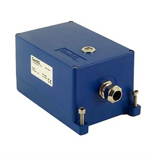


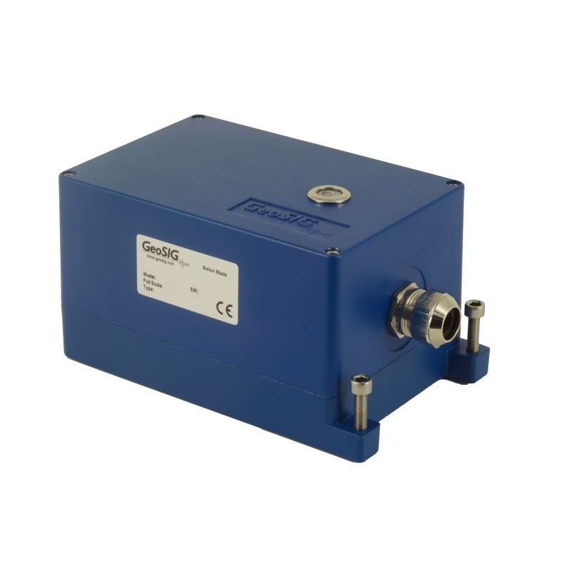
GeoSIG VE-13 Velocity Sensor
Key Features
- Wide Full Scale Range, ± 1 to ± 100 mm/s
- Bandwidth 1 Hz to 315 Hz
- Civil Engineering and general vibration measurement applications
- Built-in Impulse Test Circuit
- Single Bolt Mounted Housing provides up to ± 10° of Levelling Adjustment
The VE Velocity Sensors are engineered for consistent performance over a long lifetime. Advanced computerised testing, manufacturing techniques and quality control are used in the production process to provide both the uniform parameters and the rugged qualities required in modern velocity sensors.
The sensor module has proven itself successfully worldwide for many years in different applications. The symmetrical rotating dual coil construction minimises the force on the spring arms. The use of precious metals ensure optimum electrical contact and a long operating life. The VE Velocity Sensors operate from a wide range of input voltages and can be used for a variety of civil engineering and general vibration measurement applications.
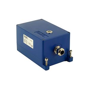
The VE-13 is a triaxial velocity sensor. The VE Velocity Sensors are housed in a very compact 195 x 112 x 95 mm case. The sealed cast aluminium housing contains an MS-style connector or a sealed cable inlet. The housing also incorporates a single bolt mount with three levelling screws, which offers extended adjusting capability during mounting.
The sensor module has proven itself successfully worldwide for many years in different applications. The symmetrical rotating dual coil construction minimises the force on the spring arms. The use of precious metals ensure optimum electrical contact and a long operating life. The VE Velocity Sensors operate from a wide range of input voltages and can be used for a variety of civil engineering and general vibration measurement applications.
The VE-13 is a triaxial velocity sensor. The VE Velocity Sensors are housed in a very compact 195 x 112 x 95 mm case. The sealed cast aluminium housing contains an MS-style connector or a sealed cable inlet. The housing also incorporates a single bolt mount with three levelling screws, which offers extended adjusting capability during mounting.
-
General Characteristics
- Application:
- Civil engineering, general vibration measurement
-
Configurations: Triaxial Biaxial Uniaxial Axes Alignment** VE-13 X X – Y – Z H – H – V - ** H: Horizontal, V: Vertical
- Full Scale Range:
- ± 100 mm/s optional: ± 1, ± 10 mm/s
-
Specification
- Instrument Type:
- Digital grade long travel geo-phones
- Dynamic Range:
- > 96 dB
- Linearity:
- < 0.3 % of full scale
- Cross Axis Sensitivity:
- < 0.1 % of full scale
- Frequency Response
- 1 to 315 Hz
- Damping
- standard 0.7
- Full Scale Output
- 0 ± 10 V differential (20 Vpp) optional 2.5 ± 2.5 V single-ended (5 Vpp) 0 to 20 mA current loop
- Output impedance:
- < 50 Ω
- Self Test:
- Impulse Test
- Measuring Range:
- See plot
.png)
-
Power
- Power supply voltage:
- 9 to 15 VDC
- Supply Current:
- 12 mA per axis
- Power Consumption:
- 26 mA typical, 31 mA max @ 15 VDC
-
Connector Pin Configuration
- Pin 1-2, 3-4, 5-6:
- Signal output for axis X, Y, Z
- Pin 7-8:
- Test input, Digital test-pulse (0 – 12 V)
- Pin 9-10:
- +12 VDC Power Supply
- Pin 11-12:
- Sensor Mode
- Case:
- Shielded Ground
-
Environment/Housing
- Housing Type:
- Cast aluminium
Sealed access cover - Housing Size:
- 195 x 112 x 95 mm
- Weight:
- 2.0 kg
- Index of Protection:
- IP 65
optional IP 68 - Temperature Range:
- -25 to 85 °C (operating)
-40 to 100 °C (storage) - Humidity:
- 0 to 100 % (non-condensing)
- Mounting
- Single bolt, surface mount, adjustable within ± 10°
.png)
-
Standard VE-1x
- Floor mounted, Full scale ± 100 mm/s 2 m cable with sensor mating connector, concrete anchor and user manual on CD
-
Options
- Cable & connector:
- Sealed cable inlet, replaces connector cable with shielded twisted pairs for any length (including mating sensor connector) with open end Cables for connection to GeoSIG recorder connector on user specification mounted at cable
- Housing:
- Watertight IP68 housing stainless steel protective housing
- Temperature Range:
- -25 to 100 °C (operating)
- Temperature Output:
- Temperature sensing at the sensor side
-
Ordering Information
- Specify:
- Type of VE-13, full scale range, and other applicable options
-
**Specifications subject to change without notice