


GeoSIG SMS / SAS
Key Features
- Recording, advanced analysis and annunciation according to project specific or international regulations
- Automatic exceedance evaluation
- Reporting and alerting via relays, visual and audible tools as well as printed matter
- Project specific Automatic Event Processing (AEP), Nuclear (NPP) or other features
- Up to 36 remote triaxial analog sensors and unlimited number of seismic field recorder stations
- 24 to 32-bit event based and/or continuous recording
- Common timing and triggering within the system
- Completely over-voltage protected
- Continuous system-wide SOH monitoring
- Seismically and EMC proven design
- Comprehensive configuration of the whole system via the enhanced computer interface
GeoSIG's SMS/SAS systems are mostly used in Nuclear Power Plant or other Industrial Facility Seismic Monitoring Projects. If you need any further specific information, please do not hesitate to contact us through our agent assigned for this kind of instrumentation for your geographical region or directly.
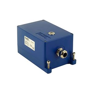
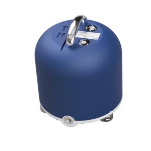
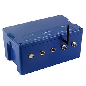
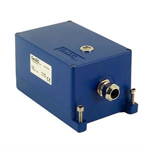
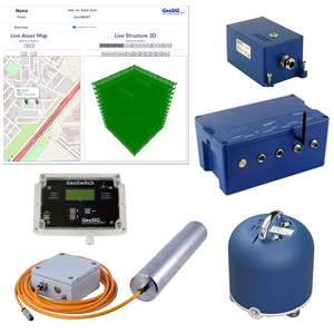
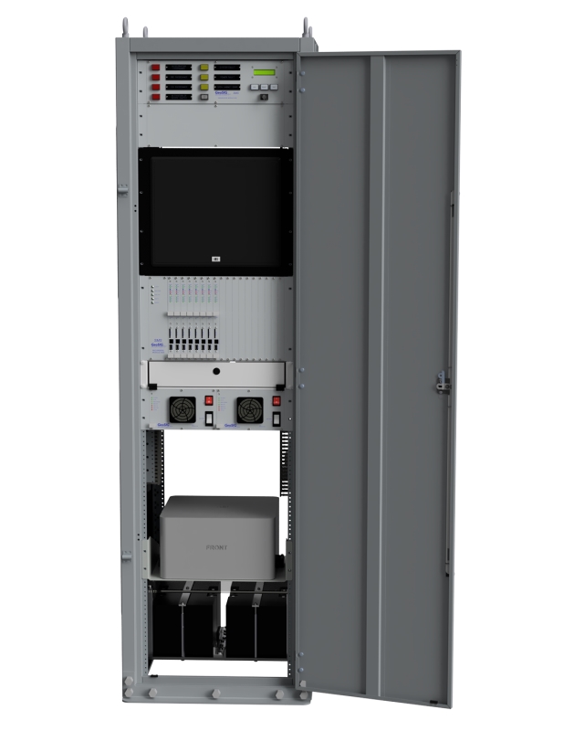
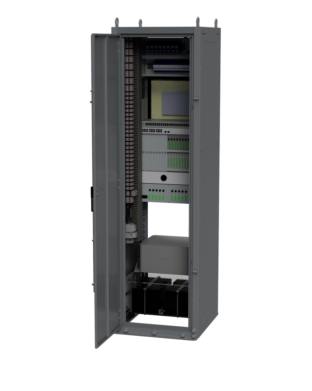
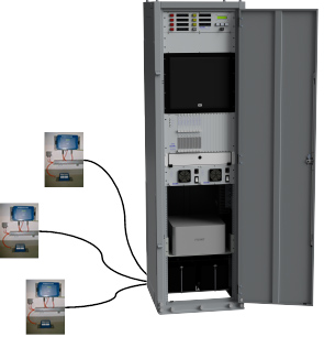
The core of the SMS / SAS is a Central Processing Unit (CPU) with a multi-channel digital recorder system rack mounted in an industrial cabinet together with an industrial computer and relevant peripherals. Accelerometers, seismometers, complete seismic stations or sensor packages, which are referred to as Detection / Recording Units (DRUs), are placed at remote locations and can be connected to the CPU.
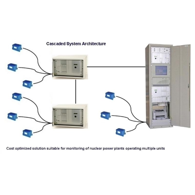
The system has been designed in a way that it is not bound to a single topology. There could be only the sensors or both sensors and data acquisition out in the field. Advantages of these topologies are briefly explained in the specifications section.
The system has great modularity and flexibility to simplify an instrumentation upgrade and enable existing elements to be reused as much as possible. The system provides added reliability with built-in redundancy of the recorders and power supply, continual SOH software checks, alerts transmitted to multiple sources, and a choice of data back-up. The PSU has quadruple redundancy of the sources. All calculations take place on each recorder, so the PC (CPU) has no critical impact on calculation and analysis of exceedances.
The CPU monitors all DRUs in parallel, as a result of the dedicated communication links that are provided by the system hardware.
By monitoring continuously the DRUs, the CPU detects seismic events, generates associated alarms and automatically processes the recorded data. Also it performs periodical tests on the system and monitors the system-wide state of the health as well as analyses the detailed cause of any malfunction. The result of the data processing is provided in a report a few minutes after the occurrence of an event.
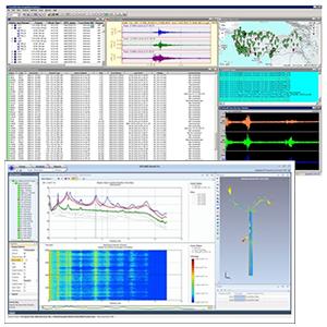
State-of-the-art GeoDAS software is utilised in the CPU. For each measuring channel the recording threshold and the alarm limit values can be set individually. Detailed project limits can be fully defined along with other parameters as required by relevant regulations or customised user requirements.
The core of the SMS / SAS is a Central Processing Unit (CPU) with a multi-channel digital recorder system rack mounted in an industrial cabinet together with an industrial computer and relevant peripherals. Accelerometers, seismometers, complete seismic stations or sensor packages, which are referred to as Detection / Recording Units (DRUs), are placed at remote locations and can be connected to the CPU.
The system has been designed in a way that it is not bound to a single topology. There could be only the sensors or both sensors and data acquisition out in the field. Advantages of these topologies are briefly explained in the specifications section.
The system has great modularity and flexibility to simplify an instrumentation upgrade and enable existing elements to be reused as much as possible. The system provides added reliability with built-in redundancy of the recorders and power supply, continual SOH software checks, alerts transmitted to multiple sources, and a choice of data back-up. The PSU has quadruple redundancy of the sources. All calculations take place on each recorder, so the PC (CPU) has no critical impact on calculation and analysis of exceedances.
The CPU monitors all DRUs in parallel, as a result of the dedicated communication links that are provided by the system hardware.
By monitoring continuously the DRUs, the CPU detects seismic events, generates associated alarms and automatically processes the recorded data. Also it performs periodical tests on the system and monitors the system-wide state of the health as well as analyses the detailed cause of any malfunction. The result of the data processing is provided in a report a few minutes after the occurrence of an event.
State-of-the-art GeoDAS software is utilised in the CPU. For each measuring channel the recording threshold and the alarm limit values can be set individually. Detailed project limits can be fully defined along with other parameters as required by relevant regulations or customised user requirements.
-
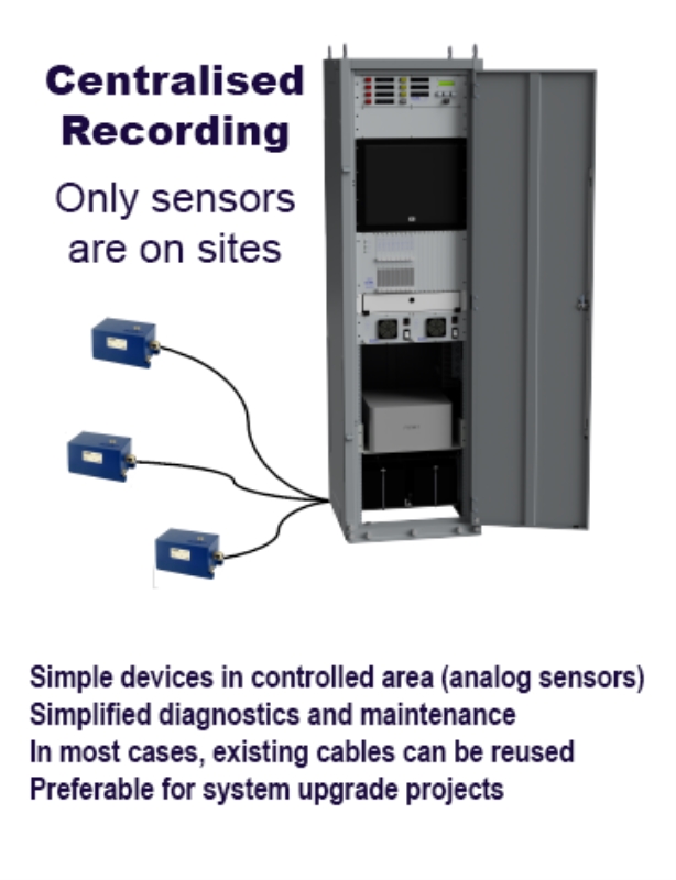
Centralised Recording
- Advantages
- Simple devices in controlled area (analog sensors) Simplified diagnostics and maintenance higher compatability with exisiting systems for upgrade
-
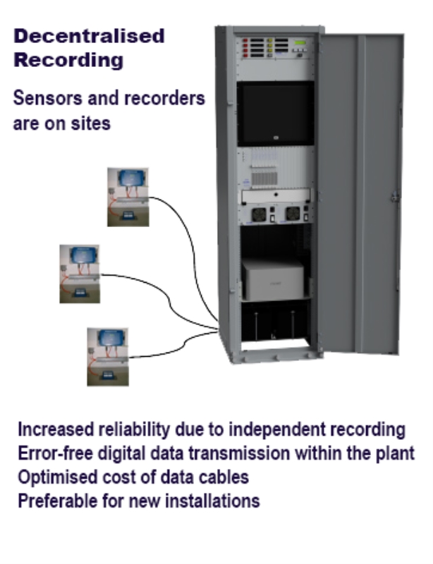
decentralised Recording
- Advantages
- Independant recording units increased redundancy and reliablility link from remote to central can use fiber optics Digital transmission between remote and central locations
-
Typical specifications
-
Sensor
- SMS/SAS system offers the most flexible sensor connectivity options to cater for the needs of any measuring requirement. Any matching type of sensor can be connected to the system.
-
Digitiser
- A/D Converter
- 24 to 32 bits
- Dynamic Range
- 137 to 150 dB @ 50 SPS
- Sampling Rates
- up to 2000 SPS
- Bandwidth
- DC to 1000 Hz
-
Data Recording
- Pre-event time
- Adjustable*
- Post-event time
- Adjustable*
-
Triggering
- type
- Level (threshold) or STA/LTA trigger, project specific triggers also available
- Filtering
- User configurable
-
Data Storage
- type
- 2 -128 GByte per 3 channels and/or HDD, SSD in the computer
-
Data Analaysis
- GeoDAS software provides various analysis functions like filtering, FFT, response spectra, etc. Other commercially available evaluation software packages may alternatively be used.
-
Timing
- Standard Clock Accuracy
- Free running, based on TCXO
- External Time interfaces
- GPS System accuracy < 1 msec.
- Indicators
- LED, Push button and/or Flatscreen indicators, may vary with each project, based on requirements
- Self Test/ State of health
- Permanently active, self monitoring and user selectable, periodical system test including comprehensive sensor, memory, filter, real time clock, battery level and hardware tests.
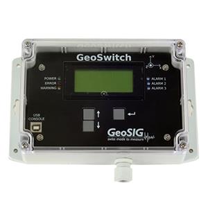
- Seismic Switch/ warning/ alarm option
- The warning option provides independent warning / error outputs (relay contacts) based on user selectable criteria. As separate acquisition module in the CPU with its own power supply, remote sensor and cable; or independent DRU’s with integral relays and CPU connection.
- Communication Channel options
- TEthernet TCP/IP, landline, GSM/ GPRS/UMTS/3G, Serial
-
Power Supply
- AC/DC Power Supply
- 230 VAC / 50 Hz or 115 VAC / 60 Hz
- External Battery option
- Rechargeable, 4 x 24 VDC, 24 to 40 Ah
- Housing
- 19’’ cabinet in different sizes, floor standing or wall mounted.
-
**Specifications subject to change without notice