























FAQ Sensors Tilt Test
1. Introduction
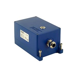
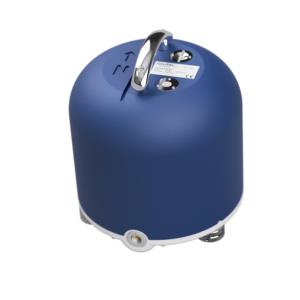
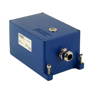
- Accelerometers AC-4X, AC-6X (legacy), and AC-7X can be tested by tilting each axis against earth gravity (±1 g). If the output is as expected, it means all axes are connected and working and the settings for LSB and fullscale are correct.
2. Required Tools
- Sensor AC-4X, AC-6X (legacy) or AC-7X
- Horizontal base (e.g. a solid table)
- Recorder / Datalogger to record sensor output
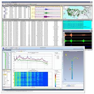
- Software to read recorded sensor output (GeoDAS is recommended.)
3. Check for Existing Procedures
- Please check if there is a project-specific procedure for your system to follow instead -- especially if your system is tied to an alarm system, as the execution of the tilt test described in this procedure may cause an alarm.
4. Remove Offset
- In GeoDAS window Stations: General Information, right-click on the station and choose Instrument Control... -> Send a Request -> REMOVEDC -> [Send]

5. Tilt Each Sensor Axis
- For better results, use the bottom part of the housing for tilting as it is with 90° angles

- Tilt the sensor with the X-axis pointing up

- Hold the position for 5 seconds
- Tilt the sensor with the X-axis pointing down

- Hold the position for 5 seconds
- Tilt the sensor with the Y-axis pointing up

- Hold the position for 5 seconds
- Tilt the sensor with the Y-axis pointing down

- Hold the position for 5 seconds
- Tilt the sensor with the Z-axis pointing down

- Hold the position for 5 seconds
- Put the sensor back in its horizontal position
6. Access Tilt Test File
- With the default setting, a miniseed file (file prefix TRG_) will be uploaded to the Data folder of your station in GeoDAS (C:\GeoDAS_DATA\Data\)
- If continuous recording (ringbuffer) is active, the tilt test will also be visible in the latest ringbuffer (file prefix RBF_) uploaded to the folder DataStreams of your station (C:\GeoDAS_DATA\Datastreams\)
7. Check Tilt Test
- Double-click the file to open it in GeoDAS
- Click into the yellow part of the window to make the cursor appear
- Move the cursor to the flat part of each pulse (see red markings in the picture below)

- Check that the value for each pulse is within the range of your sensor. (The fullscale is indicated on the sensor label.)
